

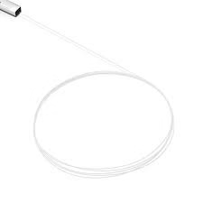
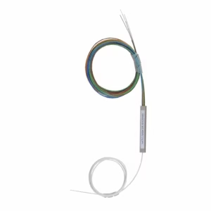
Single Mode Bare Fiber Optic PLC (Planar Lightwave Circuit) Splitters in a 1×2 configuration are passive optical devices that split one input optical signal into two equal output signals (50/50 split). Built using silica-based planar waveguide technology, these splitters offer compact size, low insertion loss, and excellent uniformity, making them ideal for passive optical networks (PON) such as FTTH, GPON, or EPON. The “bare fiber” design features unterminated 250μm fibers (no connectors), allowing direct fusion splicing into custom assemblies for space-constrained setups like splice trays or distribution boxes. They support single-mode fibers (typically G.652 or G.657) and operate across the C-band (1260-1650nm), ensuring compatibility with telecom and broadband standards.
Key Features and Specifications
- Split Ratio: 1 input to 2 outputs (equal split: ~50% power per output).
- Fiber Type: Single-mode (SMF-28 or equivalent, 9/125μm core), often G.657A1/A2 for bend insensitivity.
- Wavelength Range: 1260-1650nm (optimized for 1310nm and 1550nm).
- Insertion Loss (Typical/Max): 3.8/4.2 dB at 1310nm; 4.0/4.4 dB at 1550nm.
- Uniformity: ≤0.4 dB (channel-to-channel consistency).
- Return Loss: ≥55 dB (minimizes back-reflection).
- PDL (Polarization Dependent Loss): ≤0.2 dB.
- Directivity: ≥55 dB.
- Packaging: Compact steel tube (e.g., 40x4x4mm) or blockless ABS box for protection.
- Operating Temperature: -40°C to +85°C; storage -40°C to +85°C.
- Fiber Length: Typically 1-1.5m pigtails; bare 250μm ribbon fiber for splicing.
- Standards: Telcordia GR-1209/1221 compliant; RoHS; low PDL for stable performance.
- Applications: FTTH/GPON networks, CATV, data centers, optical signal distribution, and monitoring systems.
These specs ensure low signal degradation and high reliability (MTBF >10^6 hours) for long-term deployments.

Reviews
There are no reviews yet.